Emergency Evacuation Diagrams
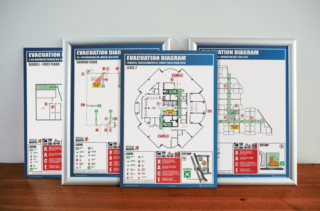
Evacuation Diagrams, Emergency Signage and Block Plans Made Easy.
All diagrams are compliant with AS3745-2010.
Evacuation diagrams that provide emergency and evacuation information shall be displayed in all facilities & failure to adhere can result in serious penalties.
Each diagram must be individually oriented to meet compliance.
WHATS INCLUDED IN AN EVACUATION DIAGRAM?
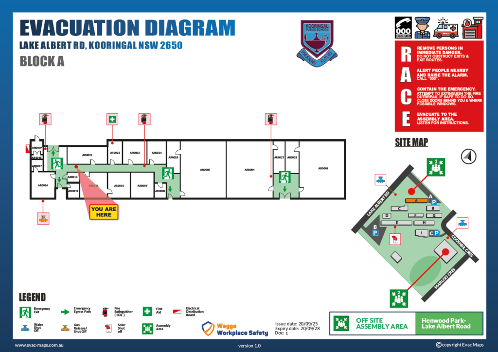
Individual evacuation diagrams shall have the correct orientation with regards to the direction of egress and its location to the ‘YOU ARE HERE’ point. Where an assembly area diagram is included, the assembly diagram are shall have the same orientation to the rest of the diagram.
Fire Evacuation Diagrams need to clearly show the evacuation path exiting the building, fir and safety equipment, emergency assembly areas and more.
ELEMENTS TO BE SUPPLIED ON DIAGRAMS:
(a) A pictorial representation of the floor or area.
NOTES:
1 Excluding external elements such as fences, roads, landscaping, external buildings, etc., unless part of the exit pathway.
2 For facilities with larger floor areas such as hospitals, tunnels, large office floors, warehouses, universities, shopping centres, etc., the pictorial representation should be prepared in sections or areas so that no more than two exits are shown on each pictorial representation.
(b) The title ‘EVACUATION DIAGRAM’.
(c) The ‘YOU ARE HERE’ location.
(d) The designated exits in the facility, which shall be green.
(e) The following communications equipment, where installed:
(i) Warden intercommunication points (WIPs), which shall be red.
(ii) Manual call points (MCPs), which shall be red and emergency call points
(ECPs), which shall be coloured white, or have a black border.
(iii) Main controls/panels for the occupant warning equipment.
(f) Hose reels, which shall be red.
(g) Paths of travel, coloured green.
(h) Extinguishers, which shall be red with an additional appropriate colour as specified in AS/NZS 1841.1.
(i) Fire blankets, which shall be coloured red.
(j) Fire indicator panel (FIP), if provided.
(k) Refuges, if present.
(l) Validity date.
(m) Location of assembly area(s), either stated in words or pictorially represented.
(n) A legend, which shall reflect the symbols used
(a) Direction of opening of doors on designated exits.
(b) North.
(c) First aid stations and kits (denoted by a white cross on a green background).
(d) Hazardous chemical store.
(e) Spill response kits.
(f) Emergency information as documented in the emergency plan. NOTE: For example, emergency telephone numbers, emergency response procedures, fire orders, and procedures for use of lifts in an evacuation during a fire emergency (where regulatory approval has been obtained).
(g) Paths of travel, coloured green.
(h) Specialised evacuation devices, including stairwell evacuation devices, if provided.
(i) Fire and smoke doors.
(j) Hydrants, which shall be red.
INSTALLING EVACUATION DIAGRAMS
Guidelines
When installing Evacuation Diagrams you have to follow the position requirements mentioned in the standard, 1200mm to 1600mm off finished floor level to the centre of the diagram.
Materials
Laminated 200GSM paper | Aluminium Snap-lock Frames | 1.2mm Brushed Aluminium | Printed Perspex ( All files are supplied in PDF format ).

Test & Tag
Periodical Testing of Electrical Equipment in line with AS/NZS 3760:2022
First Aid Training
Nationally Recognised 'Statements of Attainment' partnered with ABC First Aid, RTO 3399

